Overview
Many systems today have multiple microcontrollers on a single board. Flashing all of these during manufacturing and/or development can be very unwieldy if there are separate JTAG ports for each microcontroller, or you don’t have a flashing jig with test points for this purpose. With multiple JTAG ports, you would need to either have multiple JTAG programmers and connect/disconnect them to each port manually, or a single JTAG programmer that you manually connect/disconnect from each JTAG port and flash them individually. Even if you have a bootloader to update your microcontrollers, via say a common communications channel, you still need a way to flash the original bootloader (or re-flash it if it isn’t updateable).
Some microcontroller vendors provide alternative methods to flash their microcontrollers, e.g. UART rom bootloaders, etc. Unfortunately, these are usually even more unwieldy to use.
Solution
The JTAG specification allows for daisy-chaining separate JTAG “devices” on one port. An integrated circuit with JTAG pins / functionality (microcontroller, FPGA, etc.) can, and probably will, have multiple JTAG devices. For instance, most STM32 microcontrollers have 2 devices, one for programming (CoreSight JTAG-DP) and one for JTAG boundary scans (STM32 Boundary Scan). The limit of how many devices depends on which JTAG programmer you use, e.g. SEGGER’s J-Link has a limit of 32 devices.
You will need to ensure that your JTAG clock speed is only as fast as the maximum supported by the slowest microcontroller’s JTAG port.
If your microcontrollers don’t all use the same voltage for their JTAG I/O pins, you will need extra voltage translation circuitry.
See the JTAG Design For Test Guidelines in the References section for details on proper hardware termination of the JTAG daisy-chain.
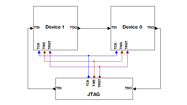
Figure 1 – Source SEGGER UM08001
To chain JTAG devices, you need to connect the TCK, TMS and TRST lines of the JTAG programmer to those pins on all the microcontrollers. Then, you need to connect the JTAG programmer’s TDI pin to the first microcontroller in the chain’s TDI pin. Then connect that microcontroller’s TDO pin to the next microcontroller in the chain’s TDI pin, and so on until the last microcontroller’s TDO pin is connected to the JTAG programmer’s TDO pin. This allows the programmer to serially communicate with every device in the chain by shifting the data through.
You will need to know a few things about each microcontroller’s “devices”, including the JTAG IRLen (Instruction Register length) of each device, and what number that device is in the chain. Some JTAG programmers can detect the IRLen, e.g. SEGGER J-Link. Once you know these, you can program a specific device in the chain.
Some debuggers / IDEs support debugging one or more microcontrollers at once in a chain. So, you can not only program, erase, etc, but debug using this method.
Note: In addition to a common JTAG port for all devices in the chain, you can also have one JTAG port per microcontroller, i.e. if you want to program and debug them separately from the chain. These would be connected as you would typically connect individual ports.
Example
As an example, in my testing, I used a chain of 6 STM32 Nucleo boards connected to a SEGGER J-Link Plus using J-Link Commander command line utility.
My chain contained:
- Nucleo-L4R5ZI
- Nucleo-L552ZE
- Nucleo-L552ZE
- Nucleo-L443RC
- Nucleo-L443RC
- Nucleo-L443RC
To get J-Link commander to list all the connected devices, attempt to connect automatically to the first available device:
J-Link> connect
Device> STM32L4R5ZI
TIF> JTAG
JTAGConf> -1, -1
Speed> <ENTER> for default
It will then dump a list of devices:
JTAG chain detection found 12 devices:
#0 Id: 0x4BA00477, IRLen: 04, CoreSight JTAG-DP
#1 Id: 0x06470041, IRLen: 05, Unknown device
#2 Id: 0x0BA04477, IRLen: 04, CoreSight JTAG-DP
#3 Id: 0x16472041, IRLen: 05, Unknown device
#4 Id: 0x0BA04477, IRLen: 04, CoreSight JTAG-DP
#5 Id: 0x16472041, IRLen: 05, Unknown device
#6 Id: 0x4BA00477, IRLen: 04, CoreSight JTAG-DP
#7 Id: 0x06435041, IRLen: 05, STM32 Boundary Scan
#8 Id: 0x4BA00477, IRLen: 04, CoreSight JTAG-DP
#9 Id: 0x06435041, IRLen: 05, STM32 Boundary Scan
#10 Id: 0x4BA00477, IRLen: 04, CoreSight JTAG-DP
#11 Id: 0x06464041, IRLen: 05, Unknown device
To program the 3rd microcontroller (the 2nd Nucleo-L552ZE) in this chain, you need to know which device to program. As you can see, each STM32 has 2 devices. The 1st device of each of these microcontrollers happens to be CoreSight JTAG-DP, which is the Debug Port for that microcontroller. Based on this information, we know we want to program the 3rd microcontroller via that port, which is device #4.
You also need to know the IRLen of every device before that device and then add them up. In this case, that’s 4 + 5 + 4 + 5 = 18. This is how many Instruction Register bits the J-Link needs to serially shift past to speak with that microcontroller’s Debug Port.
Now that we have the information we need, we can connect to that microcontroller (note, the IRLen sum is the first number in JTAGConf and the device number is the second):
J-Link> connect
Device> STM32L552ZE
TIF> JTAG
JTAGConf> 18, 4
It will display a lot of information and then be connected, returning another J-Link prompt, at which you can now program the device:
Scanning AP map to find all available Aps
...
AP[0]: Core found
AP[0]: AHB-AP ROM base: 0xE00FE000
CPUID register: 0x410FD212. Implementer code: 0x41 (ARM)
...
Cortex-M33 identified.
J-Link> loadfile <hex-filename>
To further this example, here’s a list of JTAGConf parameters to program each microcontroller in the chain:
- 0,0
- 9,2
- 18,4
- 27,6
- 36,8
- 45,10
Note: These are only examples, based on one specific microcontroller family, STM32. Other processors may have more, or less devices per IC. For example, an FPGA I’ve used before had 3 devices. You will need to determine this information to program the devices properly.
Summary
Hopefully, this Tech Note will help you streamline your manufacturing and / or development flashing and debugging of boards with multiple microcontrollers.
Recent Comments